Construction
Architectural BIM Services: Transforming Construction Workflows


The United States construction industry is undergoing a significant technological shift. Parametric design, once limited to high-end architectural studios, is now a mainstream methodology powered by Architectural BIM. Through intelligent, rule-based modeling environments like Autodesk Revit, design teams can build adaptive, data-rich models that respond dynamically to project constraints, site conditions, and structural logic. This article explores how Architectural BIM Services are redefining parametric workflows, improving coordination across disciplines, and driving smarter delivery across the AEC sector in the USA.
Parametric Design in the Context of Architectural BIM
Parametric design is a computational approach where geometric relationships, material properties, and spatial rules are defined by parameters. When one variable changes, dependent elements update automatically. In the context of Architectural BIM, this capability is embedded directly into the modeling environment.
Unlike traditional CAD, where geometry is static, Architectural BIM Modeling uses constraint-driven families, adaptive components, and shared parameters to create intelligent design objects. A curtain wall panel defined by height, width, and glazing ratio updates automatically across an entire façade when project specifications change.
For BIM Managers and Coordinators in the USA, this shift means fewer manual revisions, improved model accuracy, and better alignment between design intent and construction documentation.
Revit Architecture BIM Services
Revit Architecture BIM Services form the technical backbone of parametric design delivery in the US market. Revit’s Family Editor allows designers to build fully parametric components with nested geometry, formula-driven dimensions, and type catalogs. These families are not just visual representations but carry embedded data used for coordination, quantity takeoffs, and energy analysis.

Key technical capabilities that define Revit-based parametric workflows include:
- Shared Parameters and Project Parameters for consistent data exchange across disciplines
- Formula-driven geometry for adaptive structural and façade systems
- Type-driven families enabling rapid design iteration without redrawing geometry
- Constraint management using reference planes and dimensional locking
- Model Groups and Linked Models for federated multi-discipline coordination
These tools allow architectural teams to maintain LOD (Level of Development) compliance from LOD 200 through LOD 400, ensuring that model data matches what is required at each project phase under AIA standards.
Architectural BIM Services Are Changing Design Delivery
Architectural BIM Services in the USA are not simply about converting drawings into 3D models. They represent a complete redesign of how projects are conceived, coordinated, and documented. For AEC professionals working on complex commercial, healthcare, or infrastructure projects, BIM-driven parametric workflows provide measurable improvements across the project lifecycle.
Design Validation Through Parametric Constraints
Parametric constraints embedded in BIM models allow architects and designers to validate design decisions in real time. Structural clearances, egress widths, façade-to-floor ratios, and zoning setbacks can be encoded as rules within the model. When a design element violates a constraint, the model flags the conflict immediately, rather than during costly late-stage reviews.
Clash Detection and Multi-Discipline Coordination
According to research published by Autodesk, BIM adoption reduces RFIs (Requests for Information) and rework costs significantly on complex US construction projects, with federated coordination being a leading driver of those savings.
IFC-Based Data Exchange and Interoperability
Parametric models built in Revit can be exported to IFC (Industry Foundation Classes) format for interoperability with other platforms such as Archi CAD, Tekla Structures, and Open BIM workflows. IFC compliance ensures that parameter-rich data such as material specifications, fire ratings, and element classifications travels with the model geometry across platforms.
For Architectural BIM Services providers in the USA working on public sector and federally funded projects, IFC compliance is increasingly a contractual requirement. building SMART International maintains the IFC schema and provides certification programs that help firms demonstrate interoperability compliance.
LOD Standards and Parametric Modeling
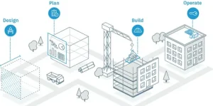
The BIM Forum LOD Specification is the standard framework used by US-based Architectural BIM Services providers to define what model elements must contain at each project stage. Parametric Architectural BIM Modeling directly supports LOD compliance because parameters can be progressively enriched as the project advances.
A typical LOD progression for architectural elements looks like this:
- LOD 200: Approximate geometry with basic material and size parameters
- LOD 300: Precise geometry with coordination-ready dimensions and shared parameters
- LOD 350: Elements include connection details and interface conditions for MEP coordination
- LOD 400: Full fabrication-level data embedded in parametric families
BIM Coordinators who manage parametric models against LOD requirements ensure that each element carries the right data at the right time, reducing model bloat and improving downstream usability for contractors and fabricators.
Benefits of Architectural BIM
AEC professionals who adopt Architectural BIM Services gain technical and operational advantages across project phases. The most significant benefits include:
- Reduced design cycle times through parametric automation of repetitive geometry
- Improved accuracy in construction documentation with constraint-driven plan and section generation
- Better change management through propagation of design updates across all views and sheets
- Enhanced collaboration via work-sharing and cloud-based BIM 360 environments
- More reliable quantity extraction using element-level parameters tied to schedules
- Compliance with US standards including AIA documents, ASHRAE energy codes, and accessibility requirements encoded as model parameters
Architectural BIM Services Provider in the USA
When selecting an Architectural BIM Services provider in the USA, AEC firms should evaluate more than software capability. The right provider must demonstrate proficiency in parametric family creation, LOD-compliant modeling workflows, IFC export standards, and federated coordination processes.
Key evaluation criteria include:
- Experience with US project delivery methods including Design-Bid-Build, Design-Build, and IPD
- Familiarity with AIA E203 BIM Protocol and project-specific BIM Execution Plans (BEPs)
- Capability to produce LOD 300 to LOD 400 Revit Architecture BIM deliverables
- Track record of clash-free federated model delivery on commercial and institutional projects
- Technical staff with Autodesk Revit certification and BIM management credentials
Conclusion
Architectural BIM is not simply a drafting upgrade. It is a fundamental restructuring of how design knowledge is created, stored, and shared across the AEC project lifecycle. By embedding parametric intelligence into building models, Architectural BIM Services enable US firms to deliver more accurate, coordinated, and data-rich projects than any traditional CAD-based workflow can support.
For Architects, BIM Managers, and Coordinators operating in the US construction market, mastering Architectural BIM Modeling through platforms like Revit is no longer optional. It is the technical foundation on which competitive, compliant, and construction-ready design delivery now rests.
Whether your firm is transitioning to BIM or scaling an existing practice, partnering with an experienced Architectural BIM Services provider in the USA delivers the parametric modeling depth, LOD compliance, and coordination capability that modern projects demand.
Author


Managing commercial, industrial, and institutional buildings with outdated 2D drawings can create unnecessary challenges. Facility teams often spend valuable time searching through old files, checking measurements, and confirming whether drawings still match the actual building. These tasks can slow maintenance, increase operating costs, and make renovation projects more difficult.
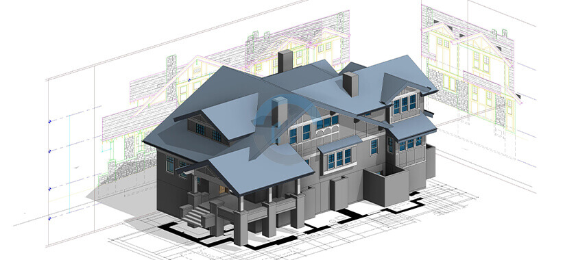
CAD to BIM technology offers a practical way to modernize this process. It transforms traditional 2D drawings into intelligent 3D models that contain useful building information. As a result, facility managers can access accurate spatial data, understand building components, and make better decisions throughout the property lifecycle.
Why Traditional 2D Drawings Create Problems
Many buildings still depend on paper plans, scanned documents, or basic CAD files. These resources can show walls, doors, rooms, and other elements. However, they rarely provide enough information for efficient facility management.
For example, a maintenance team may need to locate a specific air-handling unit or electrical panel. Staff might have to search through several drawing sets before finding the right information. Even then, the drawing may not reflect later renovations or equipment changes.
This creates uncertainty. It can also increase the risk of incorrect decisions. A digital building model can solve many of these issues. Instead of relying only on lines and labels, facility teams can work with intelligent objects that contain information about individual components.
Turning Old Drawings Into Intelligent Building Information
A successful digital conversion begins with an assessment of the available documentation. Specialists review existing CAD files, architectural plans, structural drawings, and other records. They then determine the information required for the final model.
During CAD to BIM development, modelers convert flat drawing elements into intelligent 3D components. Walls, doors, windows, columns, mechanical equipment, and other assets can receive useful information.
This information may include dimensions, materials, equipment specifications, manufacturer details, installation dates, and maintenance information. The exact data depends on the project’s goals.
The result gives facility teams a centralized digital reference. Instead of searching through disconnected documents, managers can review building information within one coordinated environment.
Improving Accuracy With Reality Capture
Old drawings do not always represent current building conditions. Tenants may have changed layouts. Contractors may have installed new equipment. Renovation projects may also have modified structural or mechanical systems. Reality capture can help address these gaps.
Laser scanners can record existing conditions and collect millions of spatial points. Specialists then process this information to create a detailed digital representation of the property.
Point cloud modeling can support accurate as-built documentation. It can reveal deviations between original drawings and current conditions. Consequently, design and facility teams gain a clearer understanding of the building before they plan modifications. This approach proves especially valuable for older properties with incomplete records.
Supporting Architectural and Structural Planning
A detailed digital model can help architects and engineers work more confidently. They can review room layouts, building dimensions, structural elements, and other important components within one environment.
Architectural teams can use the model to study available space and plan renovations. They can also evaluate circulation areas, room configurations, and building envelopes.
Structural professionals can review columns, beams, foundations, and framing systems. This information can support renovation planning and reduce the need for assumptions.
Furthermore, combining architectural and structural information improves coordination. Teams can identify potential conflicts earlier and discuss solutions before construction begins.
Making Maintenance More Efficient
Facility management teams handle countless maintenance tasks every year. Finding the right information quickly can make a significant difference. An intelligent model can help staff identify equipment locations and review related information. For example, a manager may locate an air-conditioning unit and review its specifications without searching through several folders.
The model can also support maintenance planning. Teams can connect equipment information with service schedules, warranties, and replacement plans when the project includes those details. As a result, managers can organize maintenance work more effectively. They can also reduce unnecessary delays caused by missing or outdated information.
Improving Space Management
Large organizations often manage extensive properties with constantly changing space requirements. Departments move. Tenants change. Workspaces evolve. Facility teams therefore need accurate information about available areas. A digital model can make space planning easier. Managers can review room dimensions, floor areas, and building layouts from a centralized source.
This information can support office planning, tenant coordination, renovation studies, and space allocation. It can also help organizations understand how they currently use their buildings. Therefore, digital modeling does more than improve visualization. It can support practical decisions about real estate and workplace management.

Supporting Renovation and Capital Projects
Renovation projects often become complicated when teams lack reliable existing-condition information. Contractors may discover unexpected conditions after work begins. These discoveries can lead to delays, additional costs, and design changes.
Accurate digital documentation can reduce this uncertainty.
Before a renovation starts, project teams can review the existing model and compare it with proposed designs. They can identify potential conflicts and determine whether new systems will fit within the available space.
4D BIM can add another layer of value by connecting model elements with project schedules. Managers can then visualize construction sequences and coordinate different phases more effectively.
Connecting BIM With Facility Management Systems
Modern facility teams often use CAFM, IWMS, and other digital management platforms. A well-structured BIM model can support these systems by providing organized building information.
This connection creates a stronger digital foundation for property management. Facility teams can move from isolated drawings toward a more connected information environment.
However, the model must match the organization’s actual needs. Adding excessive information can increase complexity without providing meaningful value. Therefore, project teams should define data requirements before modeling begins.
Choosing the Right Level of Detail
Not every facility project requires the same modeling depth. A simple space-planning project may need basic geometry. A complex renovation may require detailed architectural, structural, and MEP information.
The team should establish the required Level of Development or Level of Detail at the beginning. Clear requirements help control project costs and prevent unnecessary modeling work.
Similarly, teams should identify which assets require detailed information. Focusing on important equipment and systems can create a more useful model without adding unnecessary complexity.
Benefits of Professional BIM Conversion
Working with experienced modeling specialists can help organizations manage large conversion projects more efficiently. Professionals can review legacy drawings, identify inconsistencies, coordinate disciplines, and structure model data according to project requirements.
Professional CAD to BIM services can also support scalable workflows for large property portfolios. Organizations can establish consistent modeling standards across multiple buildings. This consistency makes future updates easier. It also gives different teams a common framework for managing building information.
Preparing Buildings for the Digital Future
Facility management continues to move toward connected digital environments. Digital twins, smart building systems, predictive maintenance, and automated asset management all depend on reliable building information.
Accurate BIM models can provide an important foundation for these technologies. They help organizations understand physical assets and connect building data with digital management tools. As technology develops, property owners can build on this foundation rather than starting from outdated documentation.
Final Thoughts
Modern facility management requires accurate information, efficient workflows, and reliable documentation. Traditional 2D drawings can provide useful historical records, but they often lack the intelligence needed for today’s complex property operations.
CAD to BIM creates a bridge between legacy documentation and modern digital facility management. It gives organizations a clearer view of their buildings, supports maintenance planning, improves renovation coordination, and strengthens long-term asset management.
For property owners and facility managers, the real value comes from using digital models as practical management tools. With accurate data, thoughtful modeling standards, and regular updates, organizations can make smarter decisions and manage their buildings with greater confidence.
Author


Author


Scaffolding plays an important role in construction, renovation, repair, and maintenance work. It gives workers a stable platform at height and makes it easier to move tools and materials around a site. However, every scaffold does not offer the same level of strength, mobility, or durability. The material used in its construction can directly affect how well it performs.
For contractors, choosing the right Scaffolding Materials can improve safety, reduce labor requirements, and control project costs. The right choice also depends on the type of building, expected load, project duration, and local weather conditions.
If you are working on a project in the UAE, you may also need to decide whether to purchase equipment or use scaffolding rental in Abu Dhabi. Rental can provide greater flexibility, especially when project requirements change from one site to another.
Why Scaffolding Material Matters
The material of a scaffold affects several important factors. First, it determines how much weight the structure can safely handle. Second, it influences how well the scaffold performs under heat, humidity, and other environmental conditions.
Weight also matters. Lightweight equipment can make transportation and installation easier. On the other hand, heavier materials often provide greater strength and stability.
Cost is another consideration. Buying equipment requires an initial investment. It also creates ongoing expenses for storage, maintenance, transportation, and inspections. For short-term projects, rental may offer a more practical alternative.
In Abu Dhabi, environmental conditions deserve particular attention. High temperatures, humidity, and coastal air can contribute to corrosion. Therefore, contractors should choose materials that can withstand the conditions at the project site.
Common Scaffolding Materials
Steel Scaffolding
Steel remains one of the most popular choices for demanding construction projects. It offers excellent strength and can support substantial loads when contractors install and use it correctly.
Steel also provides good durability and fire resistance. With proper care, it can serve across many projects. However, steel has one major drawback: its weight. Workers need more effort and suitable equipment to transport and assemble it.
Steel can also develop rust when exposed to moisture without adequate protection. For this reason, galvanized steel often works well in environments where corrosion presents a concern.
For high-rise buildings, industrial facilities, and major commercial developments, steel remains a reliable option. Contractors can also choose scaffolding rental in Abu Dhabi to access steel systems without purchasing and storing large quantities of equipment.
Aluminum Scaffolding
Aluminum offers a lighter alternative to steel. Workers can move, assemble, and dismantle aluminum structures more easily. This feature makes them particularly useful for jobs that require frequent repositioning.
Aluminum also resists rust and corrosion naturally. As a result, it can work well for indoor maintenance, painting, electrical work, façade cleaning, and smaller renovation projects.
However, aluminum does not normally match steel for heavy load applications. It can also cost more per unit. Therefore, contractors should avoid choosing aluminum simply because it is lightweight. They should first check the project’s load and height requirements.
Timber Scaffolding
Timber has a long history in construction and remains relevant in some traditional and specialized applications. It costs less than many metal alternatives and can be cut or adjusted when a project requires a custom fit.
Wood also does not conduct electricity, which can provide an advantage in certain work environments. However, timber requires careful inspection. Moisture, insects, rot, and physical damage can weaken the material over time.
Modern construction projects increasingly favor metal systems because they offer more predictable performance and easier standardization. Local regulations and site requirements should always guide the final decision.
Bamboo Scaffolding
Bamboo may seem unusual in the UAE, but it remains an important scaffolding material in several parts of the world. It is lightweight, flexible, renewable, and relatively affordable where local supplies are available.
Despite these advantages, bamboo has limitations. Natural variations can affect its strength, while moisture, pests, and fire can create additional concerns. It also does not provide the same level of standardization as engineered metal systems.
For these reasons, bamboo has limited use in Abu Dhabi. Still, understanding it helps contractors appreciate how different regions approach temporary access structures.

Scaffolding Systems and Material Choices
The material is only one part of the decision. Contractors must also consider the type of scaffolding system they need. Tube-and-coupler systems use individual tubes and connectors. They offer considerable flexibility and work well around buildings with unusual shapes or complex designs.
Frame scaffolding uses prefabricated sections that workers can assemble quickly. It suits projects with repetitive tasks and straightforward layouts.
System scaffolding, such as cuplock or ringlock systems, commonly uses galvanized steel. Its locking design provides strong connections and makes it suitable for larger construction and infrastructure projects.
Suspended scaffolding takes a different approach. It hangs from the building and works particularly well for façade maintenance, window cleaning, and exterior repairs on tall structures.
How to Select the Right Material
Start by looking at the project’s scale. Large construction sites often need the strength of steel, while smaller maintenance jobs may benefit from lightweight aluminum.
Next, consider how long you need the equipment. If you only require scaffolding for a few weeks or months, scaffolding rental in Abu Dhabi can reduce the financial burden of ownership.
The environment matters too. Abu Dhabi’s heat, humidity, and coastal conditions can affect metal equipment. Corrosion-resistant options can therefore provide better long-term performance.
Finally, never overlook safety requirements. Choose equipment that matches the project’s expected loads and complies with applicable UAE safety standards. Proper assembly, inspection, and use remain just as important as the material itself.
Why Rental Can Be a Smart Choice
Buying scaffolding can require considerable capital. You also need suitable storage space and a plan for regular maintenance. These responsibilities can become expensive when equipment sits unused between projects.
With scaffolding rental in Abu Dhabi, contractors can choose equipment according to the needs of each job. Rental companies may offer different sizes, systems, and materials. This flexibility can help businesses avoid investing in equipment they rarely use.
Rental can also simplify equipment management. Once the project ends, the supplier takes the equipment back. Contractors do not need to arrange long-term storage or handle every maintenance requirement themselves.
Final Thoughts
Choosing suitable Scaffolding Materials requires more than comparing prices. Contractors need to consider strength, weight, durability, environmental conditions, project duration, and safety requirements.
Steel provides dependable strength for demanding projects. Aluminum offers greater mobility for lighter work. Timber still has specialized uses, while bamboo remains relevant in certain international markets.
For UAE contractors, the right rental partner can make the selection process easier. With access to suitable equipment and flexible rental options, project teams can focus on completing their work safely and efficiently. In the end, the best Scaffolding Materials are those that match the site’s practical requirements while supporting safe and productive work.
A careful evaluation before installation can prevent unnecessary costs and delays. More importantly, it helps create a safer working environment for everyone on the construction site.
Author



Cylinder Volume: The Complete Guide to Calculating Volume Accurately

Best Bourbon Tours in Kentucky: Choosing the Right Tour for You

Cabinet Shop Drawings for Precise Fabrication and Installation

Auto Repair Digital Marketing: Grow Your Automotive Business Online

Residential Drafting Services for Remodeling and Renovation Plans

Raised Bed Soil Calculator: How Much Soil Do You Really Need?

3 Best Rhude Hoodies for UK Style 2026

Revit Drafting Solutions for Accurate BIM Projects

How to Find Mobile App Developers in Dubai for Android & iOS Apps

How Do IDA Jacket Designs Balance Function, Comfort, and Style?

Cybersecurity Consulting Company SequelNet Provides Critical IT Support Services to Medical Billing Firm, Medical Optimum

Meet the Megalodon: The Shark Star of ‘Meg 2’

Reduce Video Game Lag: Level Up Your Gaming Performance

Balancing India’s Entertainment: Cricket vs. Bollywood

Jetsetter’s Secrets: Unveiling Our Favorite Travel Hacks for a Seamless Adventure

The 5 Best Live Sports Streaming Sites: Legal and Exciting!

Hollywood Labor Unrest: The Impact of ‘What About Us?’ Strikes

Unveiling the Magic of Dream Fulfillment at the Late NBA Draft

Illuminate Your Skin: Dr. Axe Unveils Natural Remedies for Lightening Knees and Elbows

Bright Choices: Navigating the Pros and Cons of Skin Whitening Creams with Dr. Axe
-

 Business3 years ago
Cybersecurity Consulting Company SequelNet Provides Critical IT Support Services to Medical Billing Firm, Medical Optimum
-
Entertainment3 years ago
Meet the Megalodon: The Shark Star of ‘Meg 2’
-
Entertainment3 years ago
Reduce Video Game Lag: Level Up Your Gaming Performance
-
 Sports3 years ago
Balancing India’s Entertainment: Cricket vs. Bollywood
-
Entertainment3 years ago
Jetsetter’s Secrets: Unveiling Our Favorite Travel Hacks for a Seamless Adventure
-
Productivity3 years ago
The 5 Best Live Sports Streaming Sites: Legal and Exciting!
-
Art /Entertainment3 years ago
Hollywood Labor Unrest: The Impact of ‘What About Us?’ Strikes
-
Sports3 years ago
Unveiling the Magic of Dream Fulfillment at the Late NBA Draft