
Construction
Scan-to-BIM in Retrofit: Accuracy, Workflows, and Outcomes

Site teams still find themselves opening ceilings or cutting into walls only to discover that the building in front of them does not match the drawings on screen. Those mismatches create on-site clashes, urgent redesigns and change orders that push programes and budgets. Because renovation work begins from an existing asset whose “truth” is often only partially documented, scan data and modelling replace guesswork with measurements. This is why scan to BIM is now a standard part of many retrofit toolkits: it turns dense point clouds into an as-is BIM that teams can trust, coordinate against and build from.
In the sections that follow I will first explain why accuracy is particularly fragile in retrofit work, then show how laser scanning supports scan to BIM workflows, describe the main types of laser scanners for BIM in retrofit contexts and finish with practical strategies that project teams can use to convert reality capture into fewer RFIs, fewer clashes and more predictable construction outcomes.
Why Accuracy Matters in Renovation and Retrofit Projects
This section continues from the introduction by making explicit what normal looks like for accurate inputs and then showing how reality deviates.
Design teams normally expect drawings and records to reflect the physical building closely enough that spatial coordination and prefabrication work proceed without repeated site visits. When that expectation holds, teams can dimension components, plan clearances and sequence work with confidence. In retrofit projects, however, a set of common uncertainties breaks that chain of trust:
- Legacy alterations accumulate over decades without consistent record updates
- Services are frequently rerouted; risers and ceiling voids often hide undocumented piping and cabling
- Structures shift, settle, and distort, resulting in walls that are out of alignment and uneven slabs that vary from the idealized plans
- Access limitations or unsafe spaces prevent manual verification using tape or a total station
Those uncertainties cause concrete consequences. When designers make clearance assumptions that later prove false, clashes appear during fit-out; when prefabricated elements rely on idealized geometry, fit-up fails and installation stalls. Studies of construction change orders repeatedly identify missing or incorrect as-built information as a leading cause of variations and cost growth. For retrofit projects, that means inaccurate inputs directly undermine BIM’s value. Clash detection flags problems against a model that does not represent physical reality. 4D simulations misrepresent logistics, and quantity take-offs may be biased. These effects together increase rework and reduce predictability.
The next section shows how laser scanning addresses these specific uncertainties by creating a measurement-based baseline for modelling and coordination.


How Laser Scanning Supports Scan to BIM in Existing Buildings
This section follows from why accuracy matters by describing the concrete workflow teams use to convert measurements into usable BIM.
At its core, laser scanning, a tripod-mounted terrestrial laser scanner or mobile LiDAR measures millions of points on visible surfaces to create a three-dimensional point cloud. Teams then transform that raw spatial data into a semantically rich BIM through a scan to BIM workflow.
The typical workflow looks like this, and each step solves earlier mentioned problems.
- Define accuracy and LOD targets: Teams align modelling detail to decisions: tolerance-critical interfaces demand tighter geometric targets than general space planning.
- Plan scan positions and capture data: Once the stations or trajectories are placed carefully, it reduces occlusions and improves overlap. Contractors can use UAV photogrammetry or LiDAR with ground scans for exteriors.
- Register and QA the point cloud: Teams register scans into a common coordinate system, check cloud-to-cloud deviations and compare control points to flag systematic biases.
- Model the as-build BIM and validate it: Modellers fit parametric elements to the cloud, validate deviations against LOA bands and document assumptions or occluded areas.
When teams execute this workflow well, dense, validated point clouds reduce guesswork and site revisits because measurements replace assumptions. Comparative studies show that tripod TLS surveys can achieve millimetre to centimetre class results in many architectural settings. For example, local deviations as low as 2 mm. RMSE values around 9.5 mm in favourable conditions. For larger, multi-storey buildings, structured QA is essential. Because registration errors of several centimetres can still occur if control is weak. These findings underline that measurement quality and registration practice matter as much as instrument choice.
The workflow described above sets the stage to choose the right scanner type for the parts of the building that matter most. The next section compares those options.
Types of Laser Scanner for BIM in Retrofit Projects
This section builds on the scan to BIM workflow by mapping scanner choice to project roles and accuracy needs. When teams select from types of laser scanner for BIM, they trade accuracy, coverage and speed.
Four practical categories cover most retrofit needs:
- TLS – Terrestrial tripod laser scanners (TLS)
- HMLS – Mobile and handheld laser scanners
- SLAM-based indoor mapping systems such as backpack, trolley, kinematic rigs, etc.
- Drone or UAV-based photogrammetry or LiDAR scanning
Before the table, note the organising principle. Teams should treat TLS as the high-accuracy backbone where millimetre or sub-centimetre fidelity matters. Use mobile, SLAM, or UAV datasets to increase coverage and speed where centimetre accuracy is acceptable.
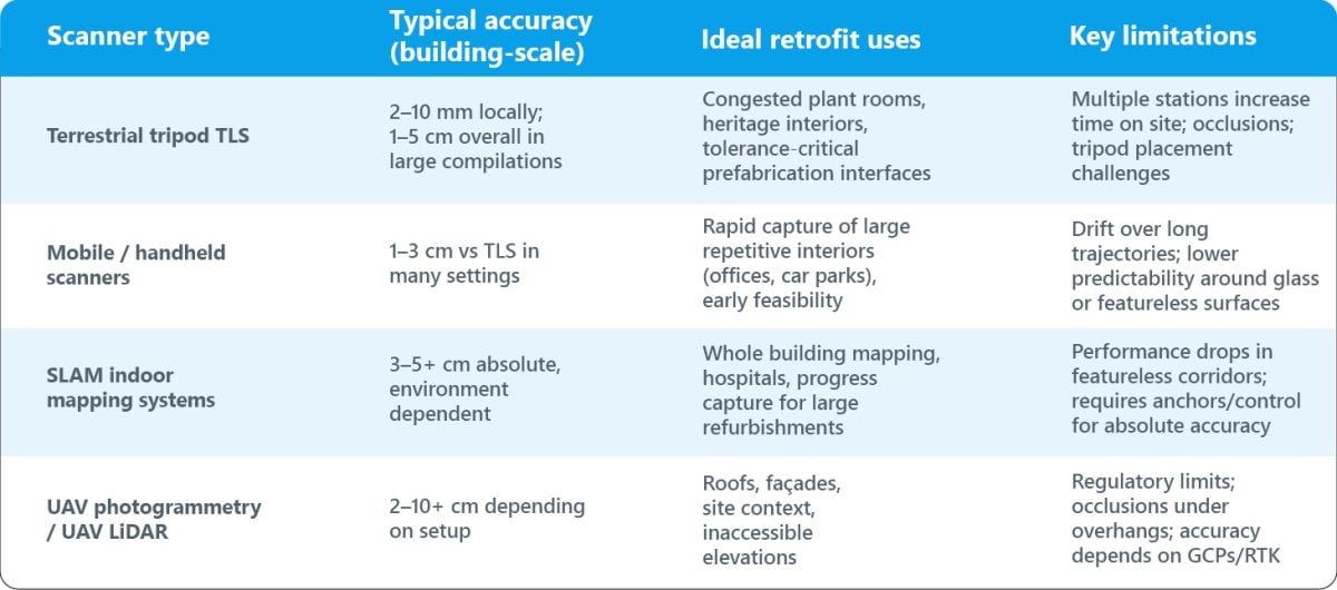
Use cases follow directly from the table. For example, teams capture plant rooms with TLS because fine clearances and complex routing demand tight dimensional control; teams choose SLAM backpacks for hospital floor surveys where speed and minimal disruption outweigh ultimate millimetre accuracy.
Strategies to Maximise Accuracy and Value from Laser Scanning
This section follows from the scanner trade-offs and explains what teams must do so scanning translates into fewer clashes and less rework.
Plan Accuracy, Scope and Access Before Tools
- Teams should define LOA classes element by element, aligning each class to a design decision. For example, bolt locations or prefabricated connections vs general room geometry. Standards and validation methods such as USIBD Levels of Accuracy help set measurable targets.
- Teams should survey access constraints early and decide whether scaffolding, UAVs or pole mounts are required. Unsafe or operational areas influence both scanner selection and the Scope Of Intrusive Verification.
Enforce Robust QA Practices
- Plan overlap and redundancy. Adequate overlap supports reliable registration and exposes misfits. For SLAM systems, design trajectories that close loops and revisit characteristic areas to constrain drift.
- Use independent control checks. Tie scans to a local control network (total station or GNSS) and test registration quality against independent checkpoints. Studies show that insufficient control is a common source of multi-storey systematic error.
- Perform cloud-to-cloud and BIM-to-cloud deviation analysis. Classify deviations against LOA bands and treat the deviation maps as engineering risk registers.
- Carry out targeted spot checks with total station or tape where consequences are high: transfer zones, stair geometry and prefabrication interfaces.
Document Assumptions and Data Gaps
- When modellers infer geometry or accept occlusions, they should mark those areas in the deliverable and the risk register so downstream teams know where intrusive investigation may still be required.
Align Scanning Strategy with Downstream BIM Use
- Teams that plan to run clash detection and fabricate off-site must prioritise TLS anchors in tolerance-critical zones.
- Teams focused on early feasibility or programme planning can accept mobile/SLAM data for whole-building context and reserve detailed TLS for install interfaces.
- Good practice: produce a scan plan that maps scanner type to each building zone, the required LOA, and a short justification so procurement and delivery teams share expectations.
Teams that combine these practices see measurable benefits. They get fewer RFIs, and get improved tolerance control in prefabricated systems. They get more predictable construction estimation sequences. A small set of comparative metrics in the literature supports this. Tripod TLS in architectural setups can reach millimetre-class local deviations. Mixed TLS and UAV workflows frequently achieve centimetre-level residuals across façades and roofs. Structured QA reduces the risk of hidden registration errors. Those errors surface during installation. Teams should reference the scanned control data in contracts. Whenever possible, also add acceptance criteria. Measurement must become the part of quality assurance in early stage.
Conclusion
Accurate as-built information is the foundation of successful retrofit projects and renovations. Design assumptions collapse when reality differs from records. A disciplined scan-to-BIM workflow that uses laser scanning gives teams a measurement-based baseline. The baseline reduces guesswork. It prevents many on-site clashes, makes coordination work. It reduces rework. Terrestrial TLS provides the highest local geometric fidelity for tolerance-critical work. Mobile, SLAM and UAV tools extend coverage and speed where centimetre accuracy suffices. Teams must choose scanner types for scan to BIM process by mapping the accuracy needs. Also, consider the physical constraints of the site.
Practical takeaway for practitioners. Define where millimetres matter and where centimetres are acceptable. Plan scanner deployments to manage occlusions and access. Treat registration and deviation analysis as contractual QA tasks. Use TLS anchors where prefabrication or tight tolerances are in play. Teams that take these steps convert reality capture into a measurable risk-reduction activity. That activity supports more reliable BIM coordination and smoother retrofit delivery.
Author




So you’re standing in your unfinished basement, looking at the bare concrete and wondering if it’s actually worth spending the money to finish it. Good question, and honestly one we hear alot. Basement Development Calgary projects are one of the most popular home upgrades in the city and there’s a good reason for that. You already own the space. The real question is whether finishing it makes sense for your home, your budget and where you see yourself in a few years.
Let’s go through the stuff that’ll help you decide.
So, Is Basement Development Worth It?
Yes, for most Calgarians. Having an unfinished basement means having more usable square footage that may generate revenue through rentals and increase your property value. It is also a good option for those who are not planning on moving anytime soon or simply need extra space.
That being said, how much its worth really depends on how the basement is built, what you use it for and whether the work is done with proper permits.
The Benefits of Basement Development in Calgary
More Space Without Moving
Moving in Calgary isn’t cheap. You’ve got realtor fees, legal costs, maybe a mortgage penalty and then all the stress of packing up your whole life. Finishing your basement gets you extra room without leaving the neighbourhood you already love.
Some of the most popular uses we see:
- Family rooms or media rooms
- Guest bedrooms
- Home offices
- Home gyms
- Play areas for the kids
- Wet bars for when friends come over
Rental Income From a Legal Suite
A legal secondary suite can go a long way toward paying down your mortgage. It has become easier for Calgary to allow the addition of suites in many areas, however, the suite requires a building permit, and there is a need to comply with safety standards such as fire separation, egress windows, and smoke detectors.
Important notice: An illegal suite can create insurance and liability concerns.
Better Resale Appeal
The idea of buying move-in ready houses is very appealing to buyers. The completion of a basement in your house will make it more attractive to the buyer.
One thing worth knowing though. Appraisers usually value below-grade space lower then above-grade space. Yes, having a finished basement will add value to your home, but that doesn’t mean you’re going to recoup all the money you spent when you sell it. You’ll get your best return on investment by utilizing the space.
Key Factors to Think About Before You Start
1. Your Budget
The cost of basement development in Calgary depends on things like:
- How big the space is
- How many bedrooms and bathrooms you want
- Whether you’re adding a kitchen or wet bar
- The quality of finishes you pick
- Plumbing and electrical needs
Set a clear budget and keep around 10 to 15 percent aside for surprises. Trust us, there’s almost always something.
2. How Long You’ll Be Staying
If your intention is to remain for at least five years, then this will definitely be very useful for you. If your plan is to sell soon, then keep it minimal.
3. Moisture and Foundation Condition
Before anyone starts framing, check for cracks, old leaks and drainage problems. Fixing moisture issues first protects everything you put in after.
4. Ceiling Height and Natural Light
Limited space due to low ceilings, heavy ductwork and small windows can restrict you from many things. The Calgary basement developers have knowledge to redirect the ductwork, install pot lighting and enlarge windows to avoid feeling of darkness in your home basement.
5. Radon Testing
Most homes in Calgary exceed the Canadian government’s health guidelines for radon levels. It is much easier to take corrective measures before the basement is completed.
6. Permits and Building Code
The City of Calgary requires a building permit to develop a basement. Plumbing, electrical and gas work might need there own permits too. Skipping them can come back to bite you with insurance or when you sell.
7. Picking the Right Contractor
Who you hire has a big impact on how much value your basement adds. When you’re comparing Calgary basement developers, look for:
- An Alberta prepaid contractor licence
- Liability insurance and WCB coverage
- Photos of past work and real reviews
- A detailed quote in writing
- A workmanship warranty
When It Might Not Be Worth It (Yet)
It could make sense to hold off if:
- Your foundation has serious water problems that haven’t been
- You’re selling in the next few months
- Your budget only allows for cheap work or skipping permits
Why Homeowners Choose Aim Builders
At Aim Builders, we assist the families in Calgary to come up with designs of Basement Development Calgary that truly make sense with their budgets and houses. This is done by dealing with all the planning, designing and construction of your basement, checking for problems relating to moisture, ventilation and design. Through the years, our company has been able to create basements in Calgary that the owners are proud of showing off.
FAQs
Is basement development worth it in Calgary?
For most homeowners, yes. It adds living space, can bring in rental income and helps with resale, especially when its done with permits.
How much does basement development in Calgary cost?
It depends on the size, layout and finishes. Adding a bathroom, kitchen or suite will bump up the price. An in-home quote is the best way to get a real number.
Does a finished basement increase my home’s value?
Yes, a permitted finished basement adds value. Just keep in mind below-grade space is usually valued lower then main floor space.
How long does basement development take?
Most projects take about six to twelve weeks, depending on size, design and how fast inspections get booked.
Do I need a permit to finish my basement in Calgary?
Yes. The City of Calgary requires a building permit, plus separate permits for plumbing, electrical or gas work when needed.
Can I rent out my basement in Calgary?
You can, as long as it’s a legal secondary suite that meets building code and has the right permits.
What adds the most value to a basement?
A bathroom, extra bedrooms with egress windows and good lighting usually add the most value and appeal.
How do I choose between Calgary basement developers?
Compare there licences, insurance, reviews, past work and written quotes. Good communication early on is a really good sign too.
What’s the difference between basement renovations Calgary homeowners do and basement development?
Development usually means finishing a basement that’s unfinished. Renovation means updating one that’s already finished. If your basement was done 20 years ago, basement renovations Calgary contractors offer can bring it up to date.
Final Thoughts
Basement renovations are often one of the wisest ways you can expand your space and increase your property’s value in Calgary. Proper planning is key, as well as solving your water issue before the actual renovations start, getting all the permits and working with experienced professionals. With these elements, your basement will become an enjoyed living space.
Thinking about Basement Development Calgary for your home? Reach out to Aim Builders today for a free consultation and let’s figure out what your basement could turn into.
Author



Introduction
The architecture, engineering, and construction industry is continually evolving as project requirements become more complex and expectations for speed, accuracy, sustainability, and cost control increase. Traditional design and construction processes often rely on fragmented drawings, manual coordination, and separate workflows between architects, engineers, contractors, and owners. These methods can create communication gaps, design conflicts, delays, and unnecessary expenses.
Building Information Modeling, commonly known as BIM, provides a more integrated approach. It combines intelligent digital models with project information to help stakeholders understand how a building will be designed, constructed, operated, and maintained. Instead of working from disconnected documents, teams can collaborate around coordinated information throughout the project lifecycle.
From improving visualization during early design to identifying clashes before construction begins, BIM technology is helping professionals make informed decisions and deliver projects with greater confidence.
Improving Design Visualization and Decision-Making
One of the most significant advantages of BIM technology is its ability to transform design concepts into detailed digital representations. Conventional 2D drawings can communicate dimensions and layouts effectively, but they may not provide every stakeholder with a complete understanding of the finished building.
BIM models provide a three-dimensional representation that allows architects, engineers, contractors, and clients to explore the proposed structure before physical construction begins. Project teams can examine spaces, building components, systems, materials, and design relationships from multiple perspectives.
Supporting Better Design Development
During design development, teams frequently need to evaluate different layouts, structural approaches, materials, and building systems. BIM makes these evaluations more efficient by providing a central environment where design information can be reviewed and updated.
Professional BIM Services can support architects, engineers, contractors, and other project stakeholders by creating coordinated models that improve visualization and provide reliable information for design and construction planning.
Because changes made within a model can be reflected across related views and documentation, teams can reduce inconsistencies that might otherwise appear when drawings are updated manually.
Strengthening Collaboration Among Project Stakeholders
Construction projects involve many disciplines working toward the same outcome. Architects develop the overall building concept, structural engineers determine how the structure will perform, building systems engineers plan essential services, and contractors determine how the project will be built.
When these teams work independently, coordination issues can easily arise. BIM creates a shared digital environment that supports better communication between disciplines.
Creating a Common Source of Project Information
A coordinated model provides stakeholders with access to consistent design information. Instead of relying on several disconnected drawings and documents, teams can use the model to understand relationships between architectural, structural, and building system components.
This collaborative approach can make project meetings more productive because potential concerns can be visualized and discussed clearly. Decisions can also be based on updated information rather than outdated drawing sets.
Better coordination during design can reduce the number of questions that need to be resolved during construction, helping teams avoid unnecessary interruptions on site.
Detecting Clashes Before Construction Begins
Design conflicts are a common source of construction delays and additional costs. A structural beam may interfere with ductwork, a pipe may conflict with another building element, or equipment may be positioned without sufficient maintenance clearance.
Finding these problems after installation has started can require redesign, material replacement, additional labor, and schedule adjustments.
BIM coordination allows teams to combine models from different disciplines and identify conflicts digitally before work reaches the construction site.
Coordinating Building Systems More Effectively
Mechanical, electrical, and plumbing systems often occupy limited ceiling, shaft, and service spaces. Careful coordination is therefore essential to make sure components can be installed without interfering with structural or architectural elements.
Specialized MEP BIM Services help project teams coordinate mechanical, electrical, plumbing, and related systems within the building model, making potential spatial conflicts easier to identify and resolve before installation.
Early clash detection reduces the need for field modifications and supports smoother construction sequencing. It can also help contractors understand installation requirements more clearly before materials and equipment arrive on site.
Supporting Accurate Construction Planning
BIM technology provides benefits beyond design coordination. Detailed models can also support construction planning by giving contractors a clearer understanding of how project components relate to one another.
Teams can use model information to study construction sequences, assess site logistics, evaluate access requirements, and prepare more detailed work plans.
Connecting Models With Project Schedules
When project models are connected with scheduling information, construction teams can visualize how the building is expected to develop over time. This approach, often associated with 4D modeling, makes it easier to understand the sequence of activities and identify scheduling conflicts.
For example, contractors can examine whether structural work must be completed before specific systems are installed or whether temporary access will be required during particular stages.
Visual construction planning also makes schedules easier to communicate to owners and other stakeholders who may not be familiar with traditional scheduling documents.
Improving Quantity Takeoffs and Cost Control
Accurate quantities are essential for estimating project costs and procuring materials. Manual takeoffs from drawings can be time-consuming and may become outdated whenever the design changes.
Because BIM models contain information about building components, they can support more efficient quantity extraction for materials such as concrete, steel, walls, doors, piping, and equipment.
Supporting More Informed Budget Decisions
When quantities are linked with cost information, teams can evaluate how design decisions may affect the project budget. Designers and owners can compare alternatives earlier and make adjustments before construction begins.
More reliable quantity information can also improve procurement planning. Contractors can determine material requirements more accurately, helping minimize excessive ordering, shortages, and avoidable waste.
Reducing Rework and Construction Risks
Rework can significantly affect construction productivity and profitability. Design errors, coordination problems, inaccurate information, and misunderstandings between disciplines can all lead to work being installed incorrectly.
By identifying problems in the digital environment, BIM allows many issues to be resolved before crews begin installation.
Improving Constructability Reviews
Contractors can review BIM models to assess whether a design is practical to construct. They can evaluate installation space, equipment access, sequencing requirements, and relationships between different trades.
This enables construction knowledge to influence decisions earlier in the project lifecycle. Addressing constructability concerns during design is generally more efficient than discovering them after materials have been fabricated or installed.
Supporting Sustainable Building Design
Sustainability has become an important consideration for modern building projects. BIM can support sustainable design by giving project teams access to structured information that can be used for performance analysis.
Designers may evaluate factors such as building orientation, energy performance, daylight availability, material quantities, and system efficiency before finalizing important decisions.
Reducing Material Waste
Accurate digital modeling and quantity information can help teams order materials more precisely. Better coordination also reduces the likelihood of components being fabricated or installed incorrectly.
When fewer materials are wasted through errors and rework, projects can improve both environmental performance and cost efficiency.
Extending BIM Benefits Beyond Construction
The value of a building model does not necessarily end when construction is completed. When properly developed and maintained, project information can support building operations and facility management.
Owners can use digital building information to better understand installed assets, equipment locations, maintenance requirements, and facility systems.
Creating Useful Information for Facility Teams
A well-organized model can become a valuable reference for maintenance and operations personnel. Instead of searching through large collections of drawings and manuals, facility teams can access structured information associated with specific building components.
This can support maintenance planning, renovations, equipment replacement, and future space modifications, extending the usefulness of BIM throughout the building lifecycle.
Conclusion
BIM technology is changing the way buildings and infrastructure are planned, designed, coordinated, constructed, and managed. By bringing project information into an intelligent digital environment, it helps architects, engineers, contractors, and owners collaborate more effectively.
Better visualization supports informed design decisions, while multidisciplinary coordination helps identify conflicts before they become costly construction problems. Accurate model information can improve scheduling, quantity takeoffs, cost planning, constructability reviews, and material management.
Author


Managing commercial, industrial, and institutional buildings with outdated 2D drawings can create unnecessary challenges. Facility teams often spend valuable time searching through old files, checking measurements, and confirming whether drawings still match the actual building. These tasks can slow maintenance, increase operating costs, and make renovation projects more difficult.
CAD to BIM technology offers a practical way to modernize this process. It transforms traditional 2D drawings into intelligent 3D models that contain useful building information. As a result, facility managers can access accurate spatial data, understand building components, and make better decisions throughout the property lifecycle.
Why Traditional 2D Drawings Create Problems
Many buildings still depend on paper plans, scanned documents, or basic CAD files. These resources can show walls, doors, rooms, and other elements. However, they rarely provide enough information for efficient facility management.
For example, a maintenance team may need to locate a specific air-handling unit or electrical panel. Staff might have to search through several drawing sets before finding the right information. Even then, the drawing may not reflect later renovations or equipment changes.
This creates uncertainty. It can also increase the risk of incorrect decisions. A digital building model can solve many of these issues. Instead of relying only on lines and labels, facility teams can work with intelligent objects that contain information about individual components.
Turning Old Drawings Into Intelligent Building Information
A successful digital conversion begins with an assessment of the available documentation. Specialists review existing CAD files, architectural plans, structural drawings, and other records. They then determine the information required for the final model.
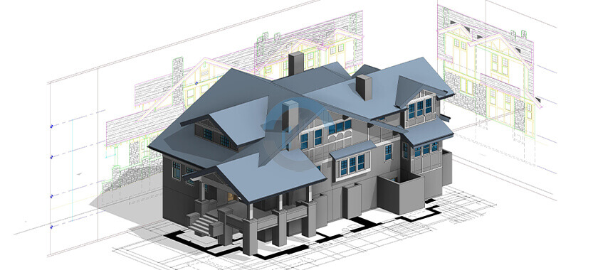
During CAD to BIM development, modelers convert flat drawing elements into intelligent 3D components. Walls, doors, windows, columns, mechanical equipment, and other assets can receive useful information.
This information may include dimensions, materials, equipment specifications, manufacturer details, installation dates, and maintenance information. The exact data depends on the project’s goals.
The result gives facility teams a centralized digital reference. Instead of searching through disconnected documents, managers can review building information within one coordinated environment.
Improving Accuracy With Reality Capture
Old drawings do not always represent current building conditions. Tenants may have changed layouts. Contractors may have installed new equipment. Renovation projects may also have modified structural or mechanical systems. Reality capture can help address these gaps.
Laser scanners can record existing conditions and collect millions of spatial points. Specialists then process this information to create a detailed digital representation of the property.
Point cloud modeling can support accurate as-built documentation. It can reveal deviations between original drawings and current conditions. Consequently, design and facility teams gain a clearer understanding of the building before they plan modifications. This approach proves especially valuable for older properties with incomplete records.
Supporting Architectural and Structural Planning
A detailed digital model can help architects and engineers work more confidently. They can review room layouts, building dimensions, structural elements, and other important components within one environment.
Architectural teams can use the model to study available space and plan renovations. They can also evaluate circulation areas, room configurations, and building envelopes.
Structural professionals can review columns, beams, foundations, and framing systems. This information can support renovation planning and reduce the need for assumptions.
Furthermore, combining architectural and structural information improves coordination. Teams can identify potential conflicts earlier and discuss solutions before construction begins.
Making Maintenance More Efficient
Facility management teams handle countless maintenance tasks every year. Finding the right information quickly can make a significant difference. An intelligent model can help staff identify equipment locations and review related information. For example, a manager may locate an air-conditioning unit and review its specifications without searching through several folders.
The model can also support maintenance planning. Teams can connect equipment information with service schedules, warranties, and replacement plans when the project includes those details. As a result, managers can organize maintenance work more effectively. They can also reduce unnecessary delays caused by missing or outdated information.
Improving Space Management
Large organizations often manage extensive properties with constantly changing space requirements. Departments move. Tenants change. Workspaces evolve. Facility teams therefore need accurate information about available areas. A digital model can make space planning easier. Managers can review room dimensions, floor areas, and building layouts from a centralized source.
This information can support office planning, tenant coordination, renovation studies, and space allocation. It can also help organizations understand how they currently use their buildings. Therefore, digital modeling does more than improve visualization. It can support practical decisions about real estate and workplace management.

Supporting Renovation and Capital Projects
Renovation projects often become complicated when teams lack reliable existing-condition information. Contractors may discover unexpected conditions after work begins. These discoveries can lead to delays, additional costs, and design changes.
Accurate digital documentation can reduce this uncertainty.
Before a renovation starts, project teams can review the existing model and compare it with proposed designs. They can identify potential conflicts and determine whether new systems will fit within the available space.
4D BIM can add another layer of value by connecting model elements with project schedules. Managers can then visualize construction sequences and coordinate different phases more effectively.
Connecting BIM With Facility Management Systems
Modern facility teams often use CAFM, IWMS, and other digital management platforms. A well-structured BIM model can support these systems by providing organized building information.
This connection creates a stronger digital foundation for property management. Facility teams can move from isolated drawings toward a more connected information environment.
However, the model must match the organization’s actual needs. Adding excessive information can increase complexity without providing meaningful value. Therefore, project teams should define data requirements before modeling begins.
Choosing the Right Level of Detail
Not every facility project requires the same modeling depth. A simple space-planning project may need basic geometry. A complex renovation may require detailed architectural, structural, and MEP information.
The team should establish the required Level of Development or Level of Detail at the beginning. Clear requirements help control project costs and prevent unnecessary modeling work.
Similarly, teams should identify which assets require detailed information. Focusing on important equipment and systems can create a more useful model without adding unnecessary complexity.
Benefits of Professional BIM Conversion
Working with experienced modeling specialists can help organizations manage large conversion projects more efficiently. Professionals can review legacy drawings, identify inconsistencies, coordinate disciplines, and structure model data according to project requirements.
Professional CAD to BIM services can also support scalable workflows for large property portfolios. Organizations can establish consistent modeling standards across multiple buildings. This consistency makes future updates easier. It also gives different teams a common framework for managing building information.
Preparing Buildings for the Digital Future
Facility management continues to move toward connected digital environments. Digital twins, smart building systems, predictive maintenance, and automated asset management all depend on reliable building information.
Accurate BIM models can provide an important foundation for these technologies. They help organizations understand physical assets and connect building data with digital management tools. As technology develops, property owners can build on this foundation rather than starting from outdated documentation.
Final Thoughts
Modern facility management requires accurate information, efficient workflows, and reliable documentation. Traditional 2D drawings can provide useful historical records, but they often lack the intelligence needed for today’s complex property operations.
CAD to BIM creates a bridge between legacy documentation and modern digital facility management. It gives organizations a clearer view of their buildings, supports maintenance planning, improves renovation coordination, and strengthens long-term asset management.
For property owners and facility managers, the real value comes from using digital models as practical management tools. With accurate data, thoughtful modeling standards, and regular updates, organizations can make smarter decisions and manage their buildings with greater confidence.
Author



Haffele Kitchen Dealer in Thrissur: Upgrade Your Home in Style

Project Capri Clothing: Hoodies, Jorts & Modern Streetwear 2026

Why Continuous Learning Matters for Business Leaders

Accurate As-Built Drawings Are the Foundation of Successful Commercial

The Best Asset Management System in UAE

Kentucky Bourbon Trail Tours What Is Included and How to Plan a Trip

Point Cloud to BIM for Renovation Projects: From 3D Scanning

Cash Only A Modern Approach to Everyday Streetwear

Balance With Dedicated Oversight From the Best Virtual Psychiatrist

Malware Protection Solutions for Business Data Security

Cybersecurity Consulting Company SequelNet Provides Critical IT Support Services to Medical Billing Firm, Medical Optimum

Meet the Megalodon: The Shark Star of ‘Meg 2’

Reduce Video Game Lag: Level Up Your Gaming Performance

Balancing India’s Entertainment: Cricket vs. Bollywood

Jetsetter’s Secrets: Unveiling Our Favorite Travel Hacks for a Seamless Adventure

The 5 Best Live Sports Streaming Sites: Legal and Exciting!

Hollywood Labor Unrest: The Impact of ‘What About Us?’ Strikes

Unveiling the Magic of Dream Fulfillment at the Late NBA Draft

Illuminate Your Skin: Dr. Axe Unveils Natural Remedies for Lightening Knees and Elbows

Bright Choices: Navigating the Pros and Cons of Skin Whitening Creams with Dr. Axe
-

 Business3 years ago
Cybersecurity Consulting Company SequelNet Provides Critical IT Support Services to Medical Billing Firm, Medical Optimum
-
Entertainment3 years ago
Meet the Megalodon: The Shark Star of ‘Meg 2’
-
Entertainment3 years ago
Reduce Video Game Lag: Level Up Your Gaming Performance
-
 Sports3 years ago
Balancing India’s Entertainment: Cricket vs. Bollywood
-
Entertainment3 years ago
Jetsetter’s Secrets: Unveiling Our Favorite Travel Hacks for a Seamless Adventure
-
Productivity3 years ago
The 5 Best Live Sports Streaming Sites: Legal and Exciting!
-
Art /Entertainment3 years ago
Hollywood Labor Unrest: The Impact of ‘What About Us?’ Strikes
-
Sports3 years ago
Unveiling the Magic of Dream Fulfillment at the Late NBA Draft